
License: CC BY 4.0
Companion to: A Cause-Oriented Cyber Threat Taxonomy: The TLCTC Framework (the v2.6 core paper) — DOI 10.5281/zenodo.20633176
DOI: 10.5281/zenodo.22697636 (concept DOI — always resolves to the latest version)
Implements: TLCTC framework specification v2.6 (canonical dictionary json-schemas/layer-1/tlctc-framework.v2.6.json); this paper is the v2.6-compatible application profile and introduces no normative content of its own.
This paper is the application companion to the TLCTC v2.6 core paper, which defines and freezes the taxonomy: ten cause-oriented threat clusters, ten axioms, the classification rules, the attack-path notation, and the two-layer (strategic/operational) model. The companion takes that taxonomy as given and shows how to put it to work. Part A addresses security operations and development audiences: it consolidates the classification procedure into an actionable sequence, condenses the cause-first decision tree, explains how to record outcomes as Data Risk Events without disturbing the cause-side classification, walks through end-to-end worked examples drawn from the published attack-path corpus, and shows how to use the MITRE ATT&CK and MITRE CWE reference mappings within the weakness → vulnerability → generic-vulnerability → cluster hierarchy. Part B addresses governance and risk audiences: it places the cause–event–consequence bow-tie in a governance context, maps the clusters and the SRE→DRE→BRE chain to the NIST Cybersecurity Framework, distinguishes local from umbrella controls, and derives velocity-adjusted detection targets together with key risk, control, and performance indicators. Part C addresses integration audiences — architects, tool owners, compliance leads, and developers — and shows the taxonomy applied across five domains: harmonizing it with other threat-modeling methods and standards (STRIDE, the Cyber Kill Chain, the Diamond Model, FAIR, D3FEND); driving multi-regime regulatory reporting from one classified path (GDPR, NIS2, DORA, CRA, IEC 62443); projecting live detection and tooling artifacts (Sigma, SARIF, SOAR, SonarQube) onto clusters; structuring secure development through the programmer/coder distinction of the Developer's View; and integrating with AI — agentic threats as a consequence amplifier and the Open Knowledge Format view that lets agents consume the framework directly. No cluster, axiom, rule, operator, or model element is redefined here; all are cited from the core.
Keywords: cyber threat classification; attack-path analysis; security operations; threat intelligence; cyber risk governance; NIST CSF; security controls; key risk indicators; detection coverage; TLCTC; threat-modeling harmonization; STRIDE; FAIR; regulatory reporting; NIS2; DORA; secure development; SSDLC; agentic AI; Open Knowledge Format
Part A — Classification in Practice
1. Introduction
The TLCTC v2.6 core paper states the framework: it derives the ten clusters by an analytical decomposition under one stated criterion — a distinct control lever and owner for each generic vulnerability — fixes the ten axioms and the classification rules, defines the attack-path notation and its boundary operators, and establishes the two-layer strategic/operational model and the cause–event–consequence bow-tie. The taxonomy is fixed there. The present paper does not extend, revise, or reinterpret it. Its purpose is narrower and complementary: to operationalize a settled taxonomy so that practitioners can apply it consistently to real work.
A taxonomy is only useful if two analysts looking at the same evidence reach the same classification, and if that classification then connects to the decisions an organization actually makes — where to place a control, how to report an incident, which indicator to watch. This paper supplies the connective tissue between the frozen definitions and those decisions. It introduces no new normative content. Every cluster, axiom, rule, operator, and model element used below is used exactly as defined in the core paper (documentation/tlctc-v2.6-core.md); where a definition is needed, it is cited rather than restated.
The paper serves three audiences, and is organized accordingly. Part A (Classification in Practice) is written for security operations and development teams — the analysts who triage incidents, the responders who reconstruct attack paths, the engineers who translate vulnerability findings into risk. It consolidates the classification procedure, condenses the cause-first decision tree, explains how to record outcomes faithfully, demonstrates the method on published incidents, and shows how to read the two large reference mappings (MITRE ATT&CK and MITRE CWE). Part B (Governance, Controls, and Indicators) is written for governance, risk, and management audiences. It places the bow-tie in a governance frame, maps the framework to the NIST Cybersecurity Framework, distinguishes local from umbrella controls, and derives velocity-adjusted detection targets and the corresponding key risk, control, and performance indicators. Part C (TLCTC Across Domains) is written for integration audiences — architects, tool owners, compliance leads, and developers. It shows the frozen taxonomy applied beyond classification and governance: harmonized with other threat-modeling methods and standards, driving regulatory reporting, projected onto detection and development tooling, structuring secure development, and integrated with AI systems and agent pipelines.
How to read this paper. Practitioners who need to classify an incident can read Part A start to finish and keep §2 (the procedure) and §3 (the decision tree) as desk references; §5 supplies models to copy. Governance readers can begin with Part B, treating §4 (outcome recording) as the bridge that explains why cause-side classification and consequence-side reporting stay separate. Either way, the core paper remains the normative authority: when this paper says "#4 Identity Theft" or "R-CRED" or "Trust Acceptance Event," the binding definition lives in the core, and any apparent conflict should be resolved in favor of the core.
2. The Classification Procedure
Classification operates on attack steps, not on incidents as a whole. An incident is decomposed into a sequence of steps, and each step is classified independently into exactly one cluster (Axiom VI). The procedure below consolidates the framework's minimal classification procedure into an actionable checklist. The classification rules referenced by ID (R-EXEC, R-ROLE, R-CRED, R-SPECIFIC, R-MITM, R-SUPPLY) are defined in full in the core paper §6; only a one-line reminder is given here.
Step 1 — Identify the attacker action and target. State plainly what the attacker did in this step, which asset or component was targeted, and what the step was trying to achieve. A step without a concrete protected asset cannot be classified; abstract descriptions ("they moved laterally") must be resolved to a specific action against a specific target before proceeding.
Step 2 — Identify the initial generic vulnerability. Ask the cause question: what root weakness did the attacker exploit to make this step succeed? The answer must map to exactly one of the ten generic vulnerabilities underlying the ten clusters — designed functional scope (#1), server-role implementation flaw (#2), client-role implementation flaw (#3), identity-artifact/credential application (#4), lack of end-to-end communication protection (#5), finite-capacity exhaustion (#6), designed execution capability for untrusted content (#7), physical accessibility (#8), human psychological factors (#9), or subverted third-party trust (#10). Classify by the cause that made this step work, not by the outcome it produced.
Step 3 — Apply the R-* rules. Check each rule for applicability and let it disambiguate:
- R-ROLE — implementation flaw? Server-role component = #2, client-role component = #3.
- R-CRED — credentials involved? Acquisition maps to the enabling cluster; application (authenticating) is always #4. Separate steps.
- R-MITM — communication-path position? Gaining position maps to the enabling cluster; interception/modification/relay is #5.
- R-SPECIFIC — can the weakness be described both as a specific generic vulnerability and as a residual one? Classify under the specific; the residual tests (#1 no flaw, #2/#3 flaw per R-ROLE) apply only when no specific one is exploited. Capacity: volume or intensity exhausting finite capacity = #6; an implementation defect causing crash/hang = #2 or #3. Channel: is the defective logic itself a communication-path control (certificate validation, chain of trust, hostname matching, expiry/revocation, channel encryption, algorithm negotiation)? Then #5; incidental defects in the same code (e.g. memory corruption in a TLS parser) stay #2/#3. Substrate: is a physical-layer property of the substrate (charge, voltage, emission, temperature, wear) the exploited vulnerability, or only the readout channel? Apply the removal test: if the property behaved ideally, would a flaw remain? Yes = #2/#3; no = #8. Attacker proximity is not the test.
- R-EXEC — does Foreign Executable Content execute here? If yes, a #7 step must be recorded at the execution moment (in addition to the enabling cluster). Domain-specific expression languages (SQL, LDAP, XPath, template syntax) are data unless they reach a general-purpose engine; natural-language instructions to a model are not FEC.
- R-SUPPLY — third-party trust link? Place #10 at the Trust Acceptance Event — the moment the trust artifact becomes authoritative inside the target domain. #10 needs the trust artifact, or its issuer, to have been subverted before acceptance; a flaw in a legitimately supplied component is classified where it is exploited, by R-ROLE or R-SPECIFIC.
Step 4 — Apply tie-breakers if needed. If more than one cluster still seems plausible, select the cluster matching the initial generic vulnerability — the weakness that made the step possible, not a downstream effect. If genuine ambiguity remains, assign the best-supported cluster and record the rationale; use the epistemic-state annotations (#X [conf=low], ?) from core §6/§7 only when no cluster can be defended.
Step 5 — Record outcomes separately as DRE. If the step produced data impact, record it as a Data Risk Event tag appended to the step (#X + [DRE: C], etc.). Outcomes never change the cluster; they are recorded alongside it. The mechanics are detailed in §4.
Step 6 — Split multi-cause steps. If what looked like one step actually contains two distinct attacker actions exploiting two different generic vulnerabilities, split it. Each resulting step maps to exactly one cluster, expressed as a path (#X → #Y). The canonical case is credential acquisition followed by credential use: two steps, two clusters, never one.
Step 7 — Document. Record the cluster assignment (in strategic and/or operational notation), a brief rationale where the classification was non-obvious, any DRE tags, the step's position in the path, and velocity annotations (Δt) where temporal evidence exists. Documentation is what makes a classification auditable and reproducible by a second analyst.
The procedure is deliberately cause-first and step-local: never classify the incident, always classify the step; never classify the outcome, always classify the weakness that the step exploited.
3. The Decision Tree
The procedure in §2 establishes what to ask; the decision tree provides a fast, ordered triage for answering it. The two are complementary — the tree is a cause-first shortcut for Steps 2 and 3, not a replacement for the full procedure. It is condensed here; the complete tree, with per-tactic guidance and worked corrections, lives in mappings/mitre-attack-enterprise/decision-tree.md.
Two prerequisites must be settled before walking the tree:
- Domain. Where does this step execute relative to the organization?
@Org→ classify.@AttackerInfraor@OtherVictims(attacker-side preparation, compromise of someone else) → N/A: it is threat potential, not a threat to this organization.@3P(a third party) → consider #10 only if a trust boundary is crossed into the environment. - Protected asset. Name a concrete asset in scope that the step affects. TLCTC requires a concrete target; an abstract technique description without a target asset cannot be classified.
The ordered questions. Walk Q1→Q10 in order and stop at the first match. The ordering is deliberate: designed-function abuse is tested before code flaws, and identity application before lower-level mechanics, so that the most common and most generic causes are caught first.
Q1  Abusing a DESIGNED function/feature/API/config, no code flaw, no foreign
    binary required?                                  → #1 Abuse of Functions
    Guard before Q2/Q3 (R-SPECIFIC, channel): is the flawed logic itself a
    communication-path control (certificate validation, hostname matching,
    revocation, channel encryption, algorithm negotiation)?
                                                      → #5 Man in the Middle
Q2  Exploiting a CODE IMPLEMENTATION FLAW, SERVER-role component?
                                                      → #2 Exploiting Server
Q3  Exploiting a CODE IMPLEMENTATION FLAW, CLIENT-role component?
                                                      → #3 Exploiting Client
Q4  Acting as a LEGITIMATE IDENTITY by presenting credentials/tokens/keys
    (credential APPLICATION, not acquisition)?        → #4 Identity Theft
Q5  Intercepting/modifying/relaying communication from a privileged position
    on the path?                                      → #5 Man in the Middle
Q6  Overwhelming finite resources by volume or intensity? (a code bug that
    crashes is #2/#3, not #6)                         → #6 Flooding Attack
Q7  Is FOREIGN CODE executing? (if launched via a legitimate tool, #1 → #7)
                                                      → #7 Malware
Q8  Physical interaction with hardware/signals, or a physical-layer property
    of the substrate itself (charge, emission, voltage)? Attacker proximity
    is not the test (R-SPECIFIC, substrate)           → #8 Physical Attack
Q9  Psychologically manipulating a human?             → #9 Social Engineering
Q10 Exploiting subverted trust in a third-party
    component/service/update (placed at the
    Trust Acceptance Event)?                          → #10 Supply Chain Attack
    └─ no match → re-examine; one of the above must apply.
Three ordering consequences are worth noting. First, because Q1 precedes Q7, the LOLBAS pattern naturally resolves to two steps: the legitimate tool invoked through its designed interface stops at Q1 (#1), and the attacker-supplied content that subsequently runs is a second step at Q7 (#7) — the #1 → #7 shape required by R-EXEC. Second, because Q4 (credential application) sits above the lower mechanics, credential acquisition is not classified here at all; it is classified by how it was acquired (a separate, earlier step) and only its use lands at Q4. Third, because the tree stops at the first match and Q2/Q3 precede Q5, the channel guard sits in front of the code-flaw questions: a certificate check that never happened is both a code defect and a failed communication-path control, and R-SPECIFIC classifies it under the specific cluster, #5, while a memory-corruption bug that merely sits in TLS code still stops at Q2/Q3. When a single observation seems to match two questions, that is the signal to split it into separate steps (Step 6 of §2), each re-entering the tree on its own.
4. Recording Outcomes in Practice
The cause–event–consequence model (core §3.4) places the ten clusters on the cause side and outcomes on the consequence side, joined by a pivot — the System Risk Event (SRE), the loss of control / system compromise, one recorded per cluster step. Consequences then follow a variable-length chain: SRE → DRE → BRE*. This section is about the practice of recording the consequence side alongside a classified step — when and how to tag — not about redefining the model, for which the core is authoritative.
The hard boundary. Outcomes are never clusters. A "data breach," a "ransomware impact," an "outage" record what happened; none of them is a generic vulnerability and none changes the cluster of the step that caused it. This is the operational form of Axiom III. In practice it means the analyst classifies the step first (§2), and only then asks whether that step also produced a data-level effect worth recording.
Tagging Data Risk Events. A DRE is recorded as a tag appended to a classified step: #X + [DRE: C], #X + [DRE: I], #X + [DRE: A]. The letters are the impacted property — Confidentiality, Integrity, Availability/Accessibility (general) — and form the refinement tree of core §7.6. When the distinction matters operationally and can be evidenced, use the refinements: for Integrity, Ii for an incorrect state (correspondence or completeness fails — the content is wrong) and If for a misattributed state (provenance or attribution fails — the record claims an origin it does not have, and its content may be perfectly accurate); for Availability, Av (data gone or unreachable — wiped, deleted) and Ac (data present but unusable — encrypted, locked behind a disabled account). Both distinctions are load-bearing for response: Ac (ransomware) leaves recovery options that Av (wiper) destroys, and Ii is answered by validation and reconciliation where If is answered by segregation of duties and provenance logging. Refinements are read off the record, never off the actor; the parent code stays legal when the refinement is unknown. Tags may be combined (+ [DRE: C, I]). A DRE is recorded at the step where the impact first occurs — confidentiality is breached at the read/collection step, not re-cited at every later staging or exfiltration step that handles the same data.
The SRE pivot, in practice. The SRE marks the moment the behavior, privileges, data, or trust relationships of a system — or of a communication relationship it takes part in — are brought outside what their owner controls, in service of an attacker's objective (core §3.4). It is not a tag on a step; it is a position in the path. Recording it matters because it opens the detection window: compromise can exist for weeks before any DRE, so naming the SRE tells responders where "we are compromised" began even when no data has yet moved. In some paths the DRE coincides with the SRE (a SQL injection that reads data the instant it succeeds); in others the SRE precedes the first DRE by days. Both are accommodated — the SRE is the pivot regardless of whether consequences are simultaneous or delayed.
BRE chaining for reporting. Beyond the DRE, business-level effects are recorded as Business Risk Events (SRE → DRE → BRE₁ → … → BREₙ): a regulatory notification, a declared outage, an imposed fine. These chain for reporting and governance (Part B), and the chain can break at any point — not every SRE yields a DRE, and not every DRE yields a BRE. In Layer-3 attack-path notation, BREs are generally narrated in prose rather than appended to steps; the notation carries the cause-side path and the DRE tags, and the business chain is reconstructed from them.
Two practitioner cautions follow directly from the boundary. First, never append a DRE to an unresolved step (?/…): without a classified cluster there is no causal basis for asserting the data effect in notation (core R-UNRES-5); record it in prose if independently confirmed. Second, never let the name of an outcome drive classification — a report that says "ransomware" still classifies the encryption execution as #7 and tags [DRE: Ac]; the brand is not the cause.
5. Worked Examples
The following three examples apply the procedure (§2), the decision tree (§3), and the outcome-recording rules (§4) end to end. Each is drawn verbatim from the published attack-path corpus; the source JSON is cited so the full step-by-step analysis can be consulted.
5.1 SolarWinds / SUNBURST (2020)
Scenario. A trojanized SolarWinds Orion update, digitally signed by the vendor, was distributed through the legitimate update channel; once installed it gave the actor a foothold from which forged SAML tokens unlocked cloud resources. Source: json-schemas/layer-3/examples/solarwinds-2020.json.
Path.
#10 ||[update][@Vendor→@Org]|| →[Δt=instant] #7 →[Δt=~14d] #4 →[Δt=~2h] #1 + [DRE: C]
Reasoning. The first step is #10 at the Trust Acceptance Event (R-SUPPLY): the cluster is placed not at the upstream vendor compromise but at the moment the signed update is accepted and becomes authoritative inside @Org — the falsifiability test holds, since declining the update would have prevented the step. The signed backdoor DLL then executing in the Orion service is a separate #7 step (R-EXEC fires; fec_executed: true), recorded at the execution moment even though delivery used a designed loading mechanism. Roughly two weeks later, forged SAML tokens are presented to authenticate — credential application, always #4 regardless of how the signing key was obtained (Axiom X / R-CRED). The final step is #1: using the now-valid identity to abuse Azure AD and Office 365 APIs as designed, with [DRE: C] recording the confidentiality breach. No code flaw appears anywhere in the path — the whole intrusion runs on trust and designed functionality.
5.2 Chaos / MuddyWater False-Flag (2026)
Scenario. An Iranian state actor used a Microsoft Teams chat impersonating IT support to harvest credentials and hijack MFA enrollment, then deployed RMM tools and an operator-gated RAT, exfiltrating data under a "Chaos ransomware" brand that performed no encryption. Source: attack-paths/chaos-muddywater-falseflag-2026.json.
Path.
#9 ||[human][@Attacker⇒@MSTeams→@Org]|| →[Δt=?] #4 →[Δt=?] #1 →[Δt=?] #4
   →[Δt=?] #1 →[Δt=~5s] #7 →[Δt=?] #7 + [DRE: C]
Reasoning. The opening step is #9, with Microsoft Teams marked as transit (⇒@MSTeams) per R-TRANSIT-3: Teams relays the deceptive content but is not itself exploited, so it is a carrier, not the attack surface. Credential acquisition happens inside the #9 step (the enabling cluster); the subsequent presentation of those credentials to the VPN/SSO is the separate #4 step (R-CRED / Axiom X). The MFA self-enrollment hijack is #1, not #4: a flawlessly implemented self-service enrollment endpoint still permits it, so the cause is designed functional scope, and folding it into the surrounding #4 chain would erase the single highest-leverage detection point. A fresh #4 records re-authentication now that the attacker controls the second factor. LOLBAS invocation of curl/installers is #1; the RMM and RAT binaries then executing are #7 (R-EXEC, including dual-use tools running attacker-controlled content). Critically, the path closes on [DRE: C] only — the "ransomware" brand is extortion pressure, not a data event; tagging [DRE: Ac] because the report says "ransomware" would violate Axiom III.
5.3 Active Directory Domain-Admin → Ransomware Cascade (2025)
Scenario. A composite reference pattern grounded in three 2025 human-operated intrusions (Lynx, Storm-2603, Storm-0300/Akira): valid credentials reach Domain Admin, the attacker harvests the directory and destroys recovery tiers, then encrypts. Source: attack-paths/ad-domain-admin-cascade-2025.json.
Path (abridged tail).
… → #4 ||[prod][@Attacker→@Org]|| → #1 → #4 → #1 … → #1 + [DRE: C] (DCSync)
   → #4 (PtH/Golden Ticket) → … → #7 + [DRE: C] (exfil) → … → #7 + [DRE: Ac] (encrypt)
Reasoning. The acquisition prefix is modeled as an unresolved gap (…, R-UNRES-8) so the one file serves all five documented variants; defenders replace it with their own classified prefix. The RDP foothold with valid credentials is #4 (clean authentication, no brute-force noise — R-CRED). The post-foothold tail is structurally #1 Abuse of Functions: enumeration, account creation, group elevation, and DCSync all invoke designed Active Directory capabilities at the authority the attacker holds. DCSync is the key teaching case — it is #1 + [DRE: C] (designed replication function abused, confidentiality breach on credential material), and its paired use (pass-the-hash or Golden Ticket presentation) is the separate #4 with no DRE, because per R-CRED the DRE attaches at acquisition, never at re-use. Two [DRE: C] subjects appear and stay distinct: credential material (DCSync) and business file data (exfiltration). Recovery destruction (vssadmin delete shadows, backup-console deletion) stays #1 + [DRE: Av] — admin tools, data gone. Finally the ransomware payload running on each host is #7 + [DRE: Ac] — data present but encrypted; "ransomware" is the outcome label, the cluster is FEC execution.
6. Using the Mappings
Two large reference mappings translate established industry taxonomies into TLCTC clusters: MITRE ATT&CK Enterprise (698 techniques) and MITRE CWE (987 weaknesses). They sit at different points of one hierarchy:
Weakness (CWE) → Vulnerability (CVE) → Generic Vulnerability (TLCTC) → Cluster (#1–#10)
A CWE names a class of flaw; a CVE is a specific instance of a CWE; TLCTC classifies by the generic vulnerability the flaw lets an attacker exploit, which resolves to one of the ten clusters. The CWE mapping enters this chain at the weakness end (translating scan and code-audit findings into strategic risk exposure); the ATT&CK mapping enters at the technique/behavior end (translating observed adversary actions into clusters). Both are reference aids for §2 — they accelerate, but do not replace, the per-step procedure, because the same label can map differently by context. §14 (Part C) extends these two static reference mappings to live operational artifacts — detection rules, scanner findings, and response playbooks.
Using the ATT&CK mapping. Each entry gives a technique a tlctcMapping in attack-path notation. A technique that resolves to a path (#1 → #7) is telling the analyst the technique spans more than one step: record both. Three illustrative rows:
| Technique | TLCTC | Why |
|---|---|---|
| T1190 Exploit Public-Facing Application | #2 |
Implementation flaw in a server-role component (R-ROLE). |
| T1078 Valid Accounts | #4 |
Credential application — authenticating with valid/stolen credentials (R-CRED). |
| T1566 Phishing | #9 |
Human psychological manipulation is the operative mechanism. |
The complete 698-technique mapping, with per-technique rationale and the cause-first decision tree, is at mappings/mitre-attack-enterprise/tlctc-enterprise-attack.json and mappings/mitre-attack-enterprise/decision-tree.md.
Using the CWE mapping. Each entry classifies a weakness by the generic vulnerability it enables; context-dependent weaknesses carry alternatives (#2 | #3) resolved at the CVE instance level by R-ROLE. Three illustrative rows:
| CWE | TLCTC | Why |
|---|---|---|
| CWE-89 SQL Injection | #2 |
Server-side code flaw enabling injection. |
| CWE-79 Cross-site Scripting | #2 → #7 | #3 |
Server-delivered script that executes client-side; DOM-based variants are a client-side flaw (#3). |
| CWE-787 Out-of-bounds Write | #2 | #3 |
Role-dependent: server-side = #2, client-side = #3 (R-ROLE). |
The full 987-entry mapping, with verdicts, rationale, and CVE references, is at mappings/mitre-cwe/tlctc-cwe.json (methodology in mappings/mitre-cwe/README.md and mappings/mitre-cwe/decision-tree.md).
A caution on the CWE mapping. Per its README, the CWE→TLCTC mapping is AI-generated and human-reviewed, and is treated as experimental. It carries an explicit verdict system — Allowed (high confidence), Allowed-with-Review (resolve at instance level), Discouraged (CWE too abstract or consequence-only), Prohibited (category/view/deprecated node) — and the verdict should be read before relying on any single row. Umbrella CWEs (e.g. CWE-20 Improper Input Validation) span multiple clusters and are deliberately not given a single cluster. For both mappings, when an entry is context-dependent or carries a path, the analyst still owns the final call via §2; the mapping is a starting point, not an oracle.
Part B — Governance, Controls, and Indicators
7. The Bow-Tie in Governance
The core paper anchors TLCTC's cause/outcome separation in a bow-tie risk structure (core §3.4): the ten clusters sit on the cause side, outcomes sit on the consequence side, and the two are joined by a pivot, the System Risk Event (SRE) — Loss of Control / System Compromise, one of which is recorded per cluster step, so a multi-step path is a chain of bow-ties. This section does not re-derive that model; it operationalizes it as the organizing frame for control placement. A complete bow-tie has five elements, and each element answers a distinct governance question.
| Element | Position | Governance role |
|---|---|---|
| Threats | Left (cause) | The initiating forces. In TLCTC these are the ten clusters; an attack path is a sequence of cluster steps on this side. |
| Preventive controls | Left | Barriers that reduce the likelihood that a cluster step reaches the central event. |
| Central event (SRE) | Knot | The decisive loss-of-control state; the pivot between cause and effect. |
| Mitigating controls | Right | Barriers that detect, contain, reduce impact, or enable recovery once compromise has occurred. |
| Consequences (DRE → BRE*) | Right (effect) | The outcome chain — Data Risk Events (loss of C/I/A) cascading into Business Risk Events (core §3.4). |
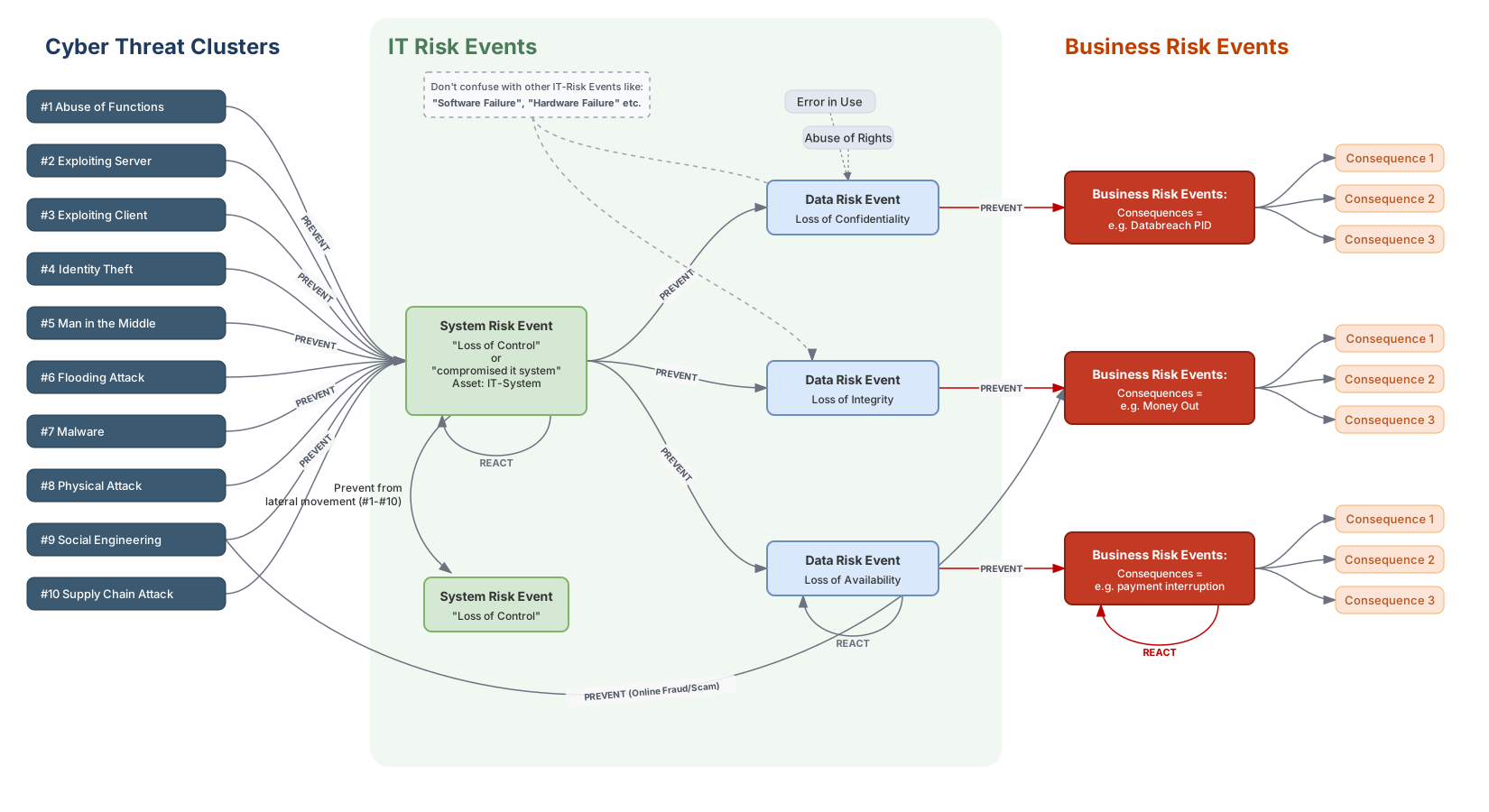
The single most consequential property for governance is that controls are placed by their position relative to the central event, not by the outcome they are imagined to prevent. A control's bow-tie position fixes both what it can do and how it is measured.
Preventive controls act on the left side. Their objective is to lower the probability that a given cluster step succeeds — input validation against #2, phishing-resistant authentication against #4, application allowlisting that denies #7 execution. These map naturally onto the IDENTIFY and PROTECT functions: a preventive control is only meaningful once the weakness enabling a specific cluster has been identified, and it is then engineered to deny that step. Because each cluster is defined by exactly one generic vulnerability, preventive controls inherit a clean per-cluster structure — the same cluster step always invites the same class of preventive objective, which is what makes control coverage comparable across systems and incidents.
Mitigating controls act on the right side, after the SRE. Their objective is no longer to stop the cluster step — that step has, by hypothesis, already reached the central event — but to compress the consequence chain: detect the loss of control, contain and eradicate it, and restore trustworthy capability before a Data Risk Event matures into a Business Risk Event. These map onto DETECT, RESPOND, and RECOVER. EDR recognizing a #7 execution, token revocation cutting short #4, and restoration from known-good backups that limits a [DRE: Ac] are all right-side controls, distinguished by which transition in the consequence chain they target.
This placement discipline yields two governance benefits. First, comparable control mapping: because threats and outcomes are held apart, every control can be assigned an unambiguous position and function, so two incidents with the same outcome but different causes — #9 → #4 versus #2, both ending in exposed data — are still analyzed and remediated against different left-side controls. Second, the detection window the SRE creates is itself a managed object: the span between compromise and consequence is where mitigating controls earn their value, and its existence is precisely why control failure is tracked on a separate dimension from threats rather than folded into an outcome label such as "breach" or "ransomware." Governance therefore reasons about two distinct levers — reduce the likelihood of reaching the SRE (left), and reduce the severity and reach of what follows it (right) — without ever conflating the cause-side cluster with the effect-side outcome.
8. Mapping to the NIST Cybersecurity Framework
The NIST Cybersecurity Framework 2.0 (CSF 2.0) organizes cybersecurity outcomes into six functions — GOVERN, IDENTIFY, PROTECT, DETECT, RESPOND, RECOVER — that name what an organization does about cyber risk. What neither the CSF Core nor its supporting risk guidance supplies is a usable answer to what a cyber threat is. NIST SP 800-30 defines a threat as:
"Any circumstance or event with the potential to adversely impact organizational operations and assets, individuals, other organizations, or the Nation through an information system via unauthorized access, destruction, disclosure, or modification of information, and/or denial of service."
The definition mentions information systems but does not distinguish cyber threats as a category of their own, and SP 800-30's threat-source taxonomy (Table D-2) offers four sources — adversarial, accidental, structural, environmental — that span all of operational risk rather than delineating cyber causes. The CSF Core itself organizes outcomes by function, not by threat type. The framework therefore asks organizations to "identify threats" and then "apply controls" without saying what constitutes a cyber threat or which controls counter which threats. Each organization fills that gap with its own vocabulary, and the resulting control mappings are neither comparable across organizations nor falsifiable within one.
TLCTC supplies exactly the missing half. The ten clusters name what was exploited: clear, distinct, non-overlapping cause categories that separate threats from vulnerabilities and impacts, and a hierarchy that links high-level risk statements to specific technical controls. Clusters are nouns (causes); CSF functions are verbs (responses); they answer different questions and never compete to classify the same thing. Anchoring the functions to the taxonomy yields five properties the function set alone cannot provide: consistency — every part of the organization speaks the same threat language; completeness — ten non-overlapping clusters ensure no cause category is silently missed; clarity — threats are communicable internally and to external stakeholders without outcome-label ambiguity; actionability — every threat category links directly to control objectives and mitigation strategies; and scalability — the same ten rows apply unchanged from a single system to the entire enterprise.
8.1 The TLCTC × CSF Control Matrix
The integration rule is simple: for each cluster #X, define control objectives and controls under each CSF function. The result is the TLCTC × CSF control matrix — ten cluster rows crossed with six function columns. Ten causes × six functions yield 60 named control objectives, and control coverage becomes falsifiable: a gap is not an abstract worry but a named, empty cell. The matrix is a structure for control objectives, not a control catalog — what changes by column is the objective type, what changes by row is the cause, the cluster's generic vulnerability — and the bow-tie of §7 fixes each function's position: IDENTIFY and PROTECT shape the cause side, DETECT and RESPOND straddle the central event, RESPOND and RECOVER act on the consequence side, and GOVERN spans the whole chain. Each cell is realized at two scopes — a local control (asset / system specific) and an umbrella control (enterprise-wide / shared), the distinction §9 develops.
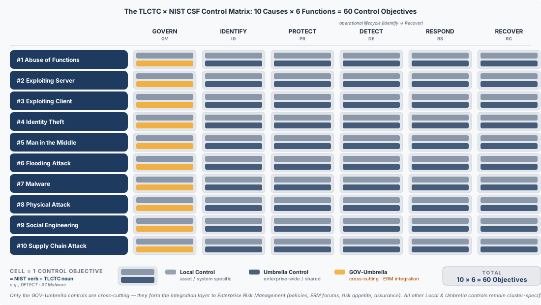
The generic template, applied identically to every cluster:
| NIST CSF Function | Control Objective | Local Controls | Umbrella Controls |
|---|---|---|---|
| GOVERN | Govern the strategy, ownership, and risk appetite for the #X cluster |
cluster-owner assignment, cluster-specific policy statement | ISMS / RMF integration, board-level risk appetite, per-cluster KRIs/KPIs |
| IDENTIFY | Identify weaknesses enabling a #X event |
specific measures targeting the threat | overarching detection systems |
| PROTECT | Protect from a #X event |
direct protection measures | enterprise-wide protection systems |
| DETECT | Detect a #X event |
local detection mechanisms | security monitoring systems |
| RESPOND | Respond to a #X event |
immediate response actions | incident-response platforms |
| RECOVER | Recover from a #X event |
local recovery procedures | business-continuity systems |
A worked example shows the template filled in; the same exercise is performed for each of the ten clusters, with control objectives, local controls, and umbrella controls chosen for the characteristics of that cause.
Worked example: #2 Exploiting Server
| NIST CSF Function | Control Objective | Local Controls | Umbrella Controls |
|---|---|---|---|
| GOVERN | Govern strategy and ownership for server-exploitation risk | AppSec / server-owner accountability, secure-SDLC policy, patch-SLA standard | risk-register entry for #2 with appetite and tolerance, vulnerability-management program (ISMS clause) |
| IDENTIFY | Identify failures in the code of the server software | fuzz testing, network-based vulnerability scanning | threat intelligence, CVE subscriptions |
| PROTECT | Protect the server from being exploited | patch management, secure coding | web application firewall (WAF) |
| DETECT | Detect an exploited server | local event logging | security information and event management (SIEM) |
| RESPOND | Respond to an exploited server | emergency patching, CSIRT engagement | exploited-server response plan (e.g., enterprise WAF-rule rollout) |
| RECOVER | Recover from a server-exploit event | maintained repositories, restore procedures | IT service continuity management (IT-SCM) |
International standards slot into this structure as a complement, not a competitor: ISO/IEC 27002's control catalogue and ISO/IEC 27005's risk-management methodology can drive the selection and implementation of the local and umbrella controls inside each function column, aligning the matrix with a certified management system.
8.2 GOVERN: The Management-System Layer
GOVERN is the specialty function of CSF 2.0, and filling the matrix per cluster makes its distinct nature obvious. The other five functions are tactical-operational: they act on the threat itself. GOVERN is strategic-integrative: it is the hook that connects each cluster into the organization's broader management system. Per cluster, GOVERN is where TLCTC plugs into an ISMS (ISO/IEC 27001, clauses 4–10) — context, leadership, planning, support, operation, performance evaluation, improvement; each cluster carries policy statements, ownership, risk acceptance, KRIs/KPIs, and management-review inputs that live inside those clauses — and into the NIST RMF (SP 800-37 / SP 800-39) — the organizational risk frame, risk tolerance, control ownership, and the link from cluster-level risk into the enterprise risk register. This is what Figure 2's highlighted band shows: the GOV-umbrella cells are the matrix's one truly cross-cutting band, its integration layer to enterprise risk management, while GOV-local — cluster owner, cluster policy, exceptions — and every other cell remain cluster-specific. Concrete GOVERN anchors per cluster:
| Cluster | GOVERN anchors |
|---|---|
#1 Abuse of Functions |
feature/abuse-case review policy, business-logic risk acceptance |
#2 Exploiting Server |
secure-SDLC policy, patch SLA, vulnerability-management program |
#3 Exploiting Client |
endpoint-hardening standard, browser/e-mail client governance |
#4 Identity Theft |
IAM policy, MFA mandate, IAM governance committee, IGA program |
#5 Man in the Middle |
cryptographic standard, TLS policy, PKI / key-management governance |
#6 Flooding Attack |
service-availability tolerance, DDoS-protection program, capacity governance |
#7 Malware |
anti-malware/EDR policy, FEC-handling rules, enterprise malware-defense program |
#8 Physical Attack |
site/asset access policy, physical-security program, facilities governance |
#9 Social Engineering |
acceptable-use and awareness policy, security-awareness program governance |
#10 Supply Chain Attack |
vendor-onboarding policy, SBOM mandate, third-party risk management (TPRM) program |
The per-cluster GOV cells are not redundant with the tactical functions: they are the steering layer that decides which local and umbrella controls in the other five columns are prioritized, funded, and reviewed for each cluster. Without GOVERN, the matrix is a control catalogue; with GOVERN, it becomes a managed system. Put concretely: PROTECT-#2 patches the server; GOVERN-#2 is the policy that says servers must be patched within n days, names the owner accountable when they are not, and feeds residual #2 risk back to the board. Both belong to cluster #2 — they operate at different altitudes.
8.3 From Matrix to Practice
The matrix tells an organization which objective each cell must satisfy for each cause, leaving the choice of specific control products to the implementer. Its practical payoff is incident learning. Given a classified attack path such as #9 → #7 → #4 → #1 → #7, an analyst walks the clusters that occurred and, for each, asks which IDENTIFY/PROTECT objective should have prevented the step, which DETECT objective should have caught it before the next step (judged against the Δt window of §10), and which RESPOND objective should have contained it. Because the same cluster always maps to the same objective row, post-incident reviews stay comparable across incidents and across the organization. To keep CSF use consistent, TLCTC is adopted as the standard cyber threat taxonomy for Risk Assessment (ID.RA): threat identification under CSF is then expressed as (cluster(s) + typical path(s)) rather than as outcome labels, and control planning references the matrix cells, which keeps the risk-assessment activity aligned with the cause-side discipline of §7.
The matrix is therefore not an illustration but the baseline concept for the system-risk layer: the layer of the bow-tie at which cluster steps are prevented, detected, and contained before a compromise matures into data and business risk events. Its floor is fixed — at minimum 60 distinct control objectives (organization-specific refinements may subdivide cells, but never merge them below the 10 × 6 grid) — and that fixed floor enables two strategic integrations. Upward, into metrics: because every cell is a named objective, the indicator system of §10 attaches directly to it — technical KCIs measure whether a cell's objective is achieved in state and coverage, procedural KCIs/KPIs measure how well it performs, and both report against risk-appetite-derived targets per cell rather than against outcome labels. Sideways, into secure development: the umbrella column, read down all ten rows, is where security architecture is defined — the enterprise's shared, deliberate capabilities (enterprise IAM, secure SDLC, SIEM/SOC analytics, resilience management) rather than an accumulation of asset-level fixes. Because architecture is the Programmer's responsibility (§15) — the role that designs the system-wide security frame, sets the secure-coding standards, and thereby oversees the Coder's implementation-side work — the umbrella column is the channel that connects governance's control matrix to the development organization: what the enterprise defines as umbrella security architecture becomes the Programmer's design constraints, and through the Programmer it reaches the code.
9. Local and Umbrella Controls
The per-cluster control objectives of §8 are realized at two different scopes, and the distinction matters for whether a control can actually act on a given attack step. Local controls protect or detect a threat on a specific asset or system (or a small set of them): host-based EDR on one server, input validation in a single application, a hardened configuration on one device. Umbrella controls operate across a wider scope — network-zone segmentation, enterprise IAM, centralized SOC monitoring, an organization-wide secure-development program. Both populate the same cluster × function cells; what differs is reach. In the worked matrix of §8.1, the "Local Controls" column lists asset-level measures (fuzz testing of one service's code, local event logging on one server), while the "Umbrella Controls" column lists shared capabilities (threat-intelligence and CVE subscriptions, the enterprise WAF, the SIEM) that serve many systems — and several clusters — at once.
The governance-critical property is that umbrella controls are always scope-limited, and frequently cannot reach an exposed patient-zero system — or become a target themselves. An internet-facing service under #2 may sit outside the protective scope of an internal WAF or the corporate EDR fleet; a phishing target under #9 may be reached on a personal device the enterprise umbrella does not cover. For initial-access clusters, therefore, an organization must verify whether the exposed surface lies inside or outside the umbrella's scope before claiming coverage. This is exactly why TLCTC's domain-boundary operator (||…||) and responsibility spheres (@X), defined in the core, carry governance weight: an umbrella control may simply not apply across a boundary that an attack path crosses.
Defense-in-depth across clusters follows directly. Because an attack path is a sequence of distinct cluster steps, a control that is strong against one cluster can be entirely bypassed by an earlier or adjacent step in a different cluster. The canonical case: #9 Social Engineering can circumvent the #4 Identity Theft controls. Phishing-resistant MFA (a #4 protective control) raises the cost of credential misuse, but a social-engineering step that induces a help-desk reset or an MFA-fatigue approval reaches loss of control without ever defeating the #4 control on its own terms — the path moved through #9 first. The governance consequence is that controls must be assessed per cluster and per path: an organization with excellent #4 coverage but weak #9 awareness controls has a defense-in-depth gap that a single-cluster control review would miss. After initial access, attacks frequently move laterally and only then enter umbrella scope, so a realistic control posture pairs local controls on exposed surfaces with umbrella controls positioned to catch the later, in-scope steps of the same path.
10. Indicators: KRI, KCI, KPI
The cluster × function matrix of §8 becomes measurable through a small hierarchy of strategic indicators, each attached to a different layer of the bow-tie and each anchored, ultimately, to the organization's risk appetite. Three indicator types and one derived measure cover the lifecycle.
KRI — Key Risk Indicators sit at the risk-event layer (the consequence side and the realized cluster steps that reach it). A KRI measures exposure to threat pressure per cluster: how often risk events and near-misses occur for a given cause. They are bounded directly by risk appetite — their thresholds are the tolerance line. Crucially, KRIs must count near-misses, not just incidents: a near-miss is a case where the threat event materialized (the attacker acted) but a control held and prevented business impact. A phishing lure that causes a user to disclose credentials, reported before the attacker ever presents them, is a realized #9 + [DRE: C] with no #4 step — per R-CRED, #4 exists only at the moment a credential is used to authenticate, so the harvested-but-unused credential is an averted → #4. That averted step is exactly the near-miss the KRI must count; it is a KRI data point, not a non-event. Examples by cluster: exploitation attempts against internet-facing services (#2), credential stuffing/spray volume (#4), malware execution attempts (#7), each split into blocked (near-miss) and successful (incident).
KCI — Key Control Indicators sit at the control-objectives layer and measure whether each objective in the matrix is achieved relative to a target derived from risk appetite. KCIs come in two forms. Technical KCIs measure state and coverage — "what is the posture?" — against a threshold target: percent of privileged accounts with hardware MFA (#4), percent of endpoints with application allowlisting (#7), percent of internet-facing services with no critical CVEs (#2). Procedural KCIs measure process performance — "how fast/well do we execute?" — against an SLA/SLO target: mean time to patch critical CVEs (#1/#2), mean time to revoke compromised tokens (#4), mean time to isolate an infected endpoint (#7).
KPI — Key Performance Indicators are, in this scheme, the procedural KCIs viewed as process-performance measures; the paper treats KPI as the performance facet of KCI rather than a separate fourth indicator type. The distinction that matters strategically is the three-way one — risk exposure (KRI), control state (technical KCI), control performance (procedural KCI/KPI) — all reporting upward against risk-appetite-derived targets.
10.1 Velocity context: the same MTTD can be effective or ineffective
A performance indicator measured in isolation is uninterpretable, because control performance is only sufficient or insufficient relative to attacker speed. Consider an identical four-hour mean time to detect (MTTD) against two attacks:
- APT campaign,
#4 →[Δt=14 days] #1: detection occurs roughly 84× faster than the attacker completes the transition (a 4-hour MTTD against a 336-hour transition). The control is highly effective — there is ample buffer. - Automated ransomware,
#4 →[Δt=10 min] #1: detection occurs ~24× slower than the transition. The same four-hour MTTD is now ineffective — the attacker wins the transition long before detection fires.
The MTTD did not change; the verdict did. The missing variable is the attack velocity Δt of the transition being defended (core §7.2).
10.2 DCS as a Key Control Indicator
The core (§7.2) defines the Detection Coverage Score as the time relationship between the defender's action and the attacker's velocity at an edge, in two forms read at the 90th percentile:
DCS_d = TTD_P90 / Δt      (detection)
DCS_c = TTC_P90 / Δt      (containment)
The core establishes DCS as a velocity relationship; here it is operationalized as a control-effectiveness KCI — the full control-indicator treatment deferred from the core. As a KCI, DCS sits between the control-objectives layer and the risk-event layer: it contextualizes raw time-to-detect and time-to-contain (procedural KCIs) by the threat reality (Δt), turning "how fast do we detect and contain?" into "do we act fast enough to matter?" Interpretation, for either form:
- DCS < 1.0 — detection (DCS_d) or containment (DCS_c) completes before the attacker completes the transition; the defender is ahead; the control is effective.
- DCS = 1.0 — detection (DCS_d) or containment (DCS_c) matches attack speed; marginal, with no buffer.
- DCS > 1.0 — the transition completes before detection or containment; the attacker wins the transition; the control is ineffective at that edge.
Detection alone does not stop a transition: DCS_d < 1 with DCS_c > 1 means the step was seen but completed anyway, so the containment form decides whether the control prevents the next step.
The two scenarios above are DCS ≈ 0.012 (APT, highly effective) versus DCS ≈ 24 (ransomware, ineffective) for the identical MTTD — the mean-based special case (MTTD / Δt, core §7.2) and the quantitative form of the velocity verdict. Read at P90 and on containment the ransomware verdict only worsens: containment follows detection and takes longer still.
10.3 Velocity-adjusted DCS targets
Because DCS is appetite-bounded, an organization sets a DCS target per velocity class, and the target then derives the required P90 detection and containment times that the procedural KCIs must meet. The velocity classes are those of core §7.2.
| Velocity class | Typical Δt | DCS target | Required TTD_P90 / TTC_P90 | Investment focus |
|---|---|---|---|---|
| Strategic (VC-1) | 7 days | ≤ 0.5 | < 3.5 days | Threat-hunting cycles |
| Tactical (VC-2) | 4 hours | ≤ 0.8 | < 3.2 hours | SOC SLA, alert tuning |
| Operational (VC-3) | 10 min | ≤ 0.8 | < 8 min | Automation, playbooks |
| Real-Time (VC-4) | 30 sec | N/A | N/A | Prevention only |
The realtime row carries the most important governance message: below roughly one minute of Δt, detection-and-response is structurally too slow regardless of MTTD investment, and the rational target is not a faster DCS but architectural prevention (rate limits, automatic isolation, design that denies the step). For all other classes the table reads top-down: risk appetite fixes the DCS target, the DCS target and the cluster's typical Δt fix the required P90 detection and containment times, and those become the procedural KCIs' SLOs.
10.4 Indicator hierarchy and axiom compliance
The indicators nest under risk appetite: appetite sets KRI thresholds (max incidents/near-misses), KCI targets (coverage, TTD and TTC), and DCS targets (per velocity class); operational raw metrics and calculated indicators feed these strategic aggregates from below. Two guardrails preserve framework integrity. First, control failure is never a threat (Axiom V): an indicator must read "lack of MFA reduces control effectiveness against #4," not "lack of MFA is a risk," and "high DCS means controls are ineffective for fast-velocity attacks," not "slow detection is a vulnerability." Second, indicators are excluded from threat statistics in the same way the framework keeps causes and outcomes apart — KRIs count realized events per cluster, but they never re-classify a cluster by its control state. This keeps the indicator system measuring the matrix without disturbing the taxonomy it measures against.
11. Risk Appetite and Business Impact
Risk appetite is the governance input that closes the loop between the consequence chain and the indicator system. It performs two jobs: it sets the thresholds against which indicators are judged, and it designates the terminal Business Impact in the consequence chain. Both follow from the cause–event–consequence model of the core (core §3.4), and neither introduces a new event type.
Setting indicator thresholds. Every target in §10 is derived from risk appetite rather than chosen in isolation. Appetite states how much risk exposure the organization will accept, and that statement propagates downward: it fixes the KRI thresholds (the maximum tolerable rate of incidents and near-misses per cluster), the KCI targets (required coverage and process performance), and the DCS targets per velocity class. The DCS target is the sharpest example of appetite expressed as a control objective — declaring "DCS ≤ 0.8 for fast-velocity attacks" is a risk-appetite decision that then derives the required P90 detection and containment times, which become measurable SLOs. Without an appetite statement the indicators have no calibrated meaning; with one, each KRI/KCI/DCS reading is a direct test of whether the organization is operating inside or outside its accepted exposure.
Designating Business Impact. On the consequence side, the chain runs SRE → DRE → BRE* (core §3.4), and Business Risk Events may cascade — a leaked database triggers a notification obligation, then media coverage, then customer churn, then a regulatory fine. Risk appetite determines at which BRE the chain reaches its terminal Business Impact (BI): the consequence threshold beyond which further causal decomposition stops being operationally useful. BI is therefore a role a BRE can hold, not a separate event type — what one organization treats as its BI (say, the notification obligation) may be a mid-chain BRE for another whose appetite tolerates more downstream consequence before declaring the terminal point. The framework supplies the chain structure; appetite supplies the cut.
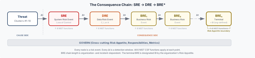
These two jobs are the same governance lever viewed from both sides of the bow-tie. On the cause side, appetite-derived DCS and KRI thresholds govern how hard the organization works to keep an attack path from reaching the SRE and progressing along it. On the consequence side, the BI designation fixes how far down the BRE chain the organization is willing to let an event run before it counts as a material loss. Tying the governance targets of §10 back to the consequence chain in this way keeps risk reporting coherent: a breached KRI threshold and a realized terminal BI are two expressions of the same appetite boundary, one measured as exposure and one observed as impact.
Part C — TLCTC Across Domains
Parts A and B operationalized the taxonomy for two audiences — analysts who classify and the governance functions that act on those classifications. Part C turns outward to a third: the architects, tool owners, compliance leads, and developers who must connect TLCTC to a method, a regulation, a tool, or a pipeline they already run. Each section takes one such domain and shows the same move — supply the cause layer the domain lacks, and let the ten clusters and the attack-path notation carry across the boundary. As in Parts A and B, nothing here is new taxonomy: every section consolidates published material and cites the core paper or a canonical artifact.
12. Harmonizing Threat-Modeling Methods & Standards
TLCTC is routinely mistaken for a competitor to the established threat-modeling methods. It is not. Each of those methods is strong on one axis and silent on another, and the axis they most often leave implicit is cause: STRIDE enumerates properties an attacker violates (effects), the Cyber Kill Chain and PASTA describe a process, FAIR quantifies frequency and loss without supplying the discrete threat categories the math needs, and the Diamond Model relates actor, capability, infrastructure, and victim without giving the capability vertex any internal causal structure. TLCTC occupies exactly that empty slot — a mutually exclusive cause taxonomy — and leaves each method's own strength untouched. The result is harmonization, not replacement: a STRIDE finding, a Kill-Chain phase, or a FAIR threat-event category each gains a cluster, and the cluster makes findings from different methods comparable.
| Method / standard | What it is (primary axis) | The gap | What TLCTC supplies |
|---|---|---|---|
| STRIDE | Property-threat checklist (Spoofing…Elevation) | Properties are effects, not causes | One cause cluster per step; a single STRIDE property spans several clusters |
| Cyber Kill Chain | Linear process phases | Process ≠ taxonomy; no per-step cause | Clusters per phase plus attack-path notation |
| Diamond Model | Relational intrusion vertices | The capability vertex lacks internal causal structure | Cause structure for "capability" |
| FAIR | Quantitative risk (LEF × LM) | Needs discrete threat-event categories to populate frequency | Clusters as the threat-event categories that feed LEF |
| MITRE D3FEND | Defensive countermeasure graph | Threat-axis gap | The cluster as the threat axis countermeasures map to |
| VERIS | Incident-description vocabulary | Cause is implicit in the action grid | A cause cluster per recorded action |
Worked illustration — one STRIDE letter, three clusters. "Tampering" classifies differently by cause: tampering achieved through a server-side code flaw is #2; tampering achieved by modifying data in transit from an on-path position is #5; tampering achieved by writing data with a stolen credential is #4. The STRIDE property is stable; the cause — and therefore the control that prevents it — is not. Mapping the property to a cluster is what tells the defender which control to reach for.
Caveat. TLCTC fills the threat-taxonomy slot and only that slot. It does not replace FAIR's quantification, the Kill Chain's sequencing, or SABSA's architectural method; it makes them cause-aware. Where a method already carries a partial cause notion (e.g. ATT&CK techniques), the existing reference mapping (§6) is the bridge. The FAIR pairing is developed further in documentation/tlctc-fair-integration-proposal.md.
13. Regulatory & Compliance Reporting
The cause–event–consequence chain of §4 and §11 is also a reporting backbone. A regulation does not, in practice, ask "what was the root cause?" in the taxonomic sense — it fixes a trigger point somewhere on the chain and attaches an obligation to it. GDPR triggers on a personal-data effect (a Data Risk Event touching PII); NIS2 triggers on a significant incident, which corresponds to the System Risk Event — loss of control — irrespective of whether any data moved; DORA triggers on ICT operational impact, a Business Risk Event, and cares about how fast it propagated. Because one classified attack path carries the cluster causes, the SRE pivot, the DRE tags, and the BRE chain all at once, the same path can satisfy several regimes without being re-described once per regulator. TLCTC supplies the shared vocabulary that maps each regime to its trigger point on a single artifact.
| Regime | Trigger point on the chain | What TLCTC supplies |
|---|---|---|
| GDPR (Art. 33/34) | Personal-data DRE (C/I/A of PII) | Cause cluster + DRE tag naming the breached property |
| NIS2 | "Significant incident" ≈ SRE (loss of control) | The cluster path that establishes the incident and its cause |
| DORA | ICT operational impact ≈ BRE + velocity | The BRE chain plus Δt for the resilience view |
| CRA | Product weakness, pre-event | CWE → cluster exposure on the left (cause) side |
| IEC 62443 | OT threat-identification gap in the risk method | Clusters + velocity classes as the threat layer for the TARA |
Worked illustration — one path, two regulators. Consider #9 ||[human][@Attacker⇒@SMSProvider→@Org]|| → #4 → #1 + [DRE: C]. NIS2 triggers at the SRE — the moment the attacker reaches loss of control after #4 — and is satisfied by reporting the cluster path. GDPR triggers later, at the [DRE: C] node, when personal data is exposed, and is satisfied by reporting the same path's DRE tag and breached property. Neither obligation requires a second incident narrative; they read different nodes of one classified path.
Caveat. TLCTC supplies the threat and trigger vocabulary, not the legal thresholds, notification timelines, or materiality cuts — those remain regime-specific and are set by counsel, not by the taxonomy. A proposed national-reporting profile, TLCTC+, operationalizes this mapping with additive Business-Risk-Event tags; it is a proposal, not part of the frozen core, and is cited here as related work (documentation/tlctc-plus-specification.md, documentation/tlctc-plus-ncsc-proposal.md). The standing control obligations that regulations impose across event chains are treated in documentation/propagated-controls.md.
14. Detection & Tooling Integration
§6 read two static reference mappings (ATT&CK, CWE) to translate a technique or a weakness into a cluster. The same cause-projection works on the live artifacts an operations or development team already produces — and turns each pile of findings into a cluster-level coverage picture. A SIEM's detection rules, a scanner's findings, and a SOAR platform's playbooks all gain a cluster, and once they share that axis the organizing principle inverts: one response playbook per cause, not one per outcome. The repository ships these projections as concrete artifacts rather than prose.
| Artifact / tool | What it emits | TLCTC projection | Canonical artifact |
|---|---|---|---|
| Sigma | Detection rules | Cluster-level coverage map (two-hop via ATT&CK) | mappings/sigma/tlctc-sigma.json |
| SARIF | Static-analysis findings | Per-finding cluster (via CWE → cluster) | integrations/sarif/cli/ |
| Cortex XSOAR / XSIAM | Response playbooks | One master playbook per cluster, velocity-routed | integrations/cortex-xsoar/, integrations/cortex-xsoar-8/ |
| SonarQube | SAST findings (CWE) | Cluster via the CWE map | integrations/sonarqube/ |
| Splunk / Cisco | Detections & telemetry | Cluster mapping | mappings/splunk-cisco/ |
Worked illustration — a finding becomes a cause. A SARIF result whose ruleId carries CWE-89 (SQL injection) projects through the CWE → cluster map to #2 Exploiting Server, and lands in the coverage view beside every other finding tagged by cause. A thousand undifferentiated findings become "N findings enabling #2, M enabling #4" — the same reframing the development view applies in §15.
Caveat. A two-hop, mechanically derived map (Sigma → ATT&CK → cluster) inherits the limits of the mapping it rides on; these projections are coverage audits, not per-incident classifications. When an artifact is context-dependent, the analyst still owns the final call via the §2 procedure — the projection accelerates triage, it does not replace it. Integration details and conformance notes are in integrations/README.md.
15. Secure Development (SSDLC): Programmer vs Coder
Every TLCTC cluster definition carries a sixth field, the Developer's View, and it splits secure development into two roles with distinct cluster responsibilities. The Programmer works on the cause (left) side of the bow-tie — architecture and strategy — and holds primary responsibility for clusters #1, #4, #5, and #10 at an architectural level: what functionality exists and how it could be misused, which authentication and communication architectures are chosen, which third-party trust is accepted. The Coder works at the centre, the event — implementation and craftsmanship — and holds primary responsibility for #2 and #3, and the implementation details of #4, #5, and #7. The division is deliberately not a clean partition: #4 and #5 are co-owned, architected by the programmer and implemented by the coder, which is precisely TLCTC's #1-by-design versus #2/#3-by-implementation logic projected onto roles. In one line: the programmer prevents the generic vulnerability from being architected into the system; the coder prevents the specific vulnerability from being written into the code. Making each SSDLC phase emit cluster-tagged deliverables is what turns "secure by design" from a slogan into a discipline.
| SSDLC phase | Owning role | Clusters emphasized | Primary control |
|---|---|---|---|
| Requirements | Programmer | Cluster-coverage matrix (all ten in/out); misuse cases (#1) | Cluster-tagged threat model + attack-path hypotheses |
| Design / Architecture | Programmer | #1, #4, #5, #10 (architectural decisions) | Attack-path design review with named interruptions |
| Implementation | Coder | #2, #3 + implementation details of #4, #5, #7 | Code review, SAST, CWE → cluster, cluster-tagged commits |
| Testing / Verification | Both | All clusters; verify the interruptions hold | SAST / DAST / SCA / fuzzing, each mapped to its cluster(s) |
| Deployment | Both | #1 baseline, #4 secrets, #5 TLS, #6 rate-limits, #10 → #7 signing | Cluster-mapped operational controls |
| Maintenance / Decommission | Both | Cluster-tagged metrics; #4 revoke, #8 wipe, #10 notify | Incident-as-attack-path; de-provisioning |
Worked illustration — the interruption table. The design-review artifact is an attack path with a named interruption at every step. Walking #9 → #4 → #1 → #7 in review: phishing #9 is interrupted by phishing-resistant MFA ✔; stolen credentials #4 by device-bound tokens ✔; abuse of admin APIs #1 by step-up authentication — ✘ gap; malware #7 by an EDR allowlist ✔. A step without a named interruption is not a diagram annotation; it is the review's finding.
Caveat. Programmer versus coder is a responsibility lens drawn from the Developer's View — it assigns ownership and selects the review type; it does not change the cluster, which is still fixed by the generic vulnerability (Axiom VI). The same CWE-787 is #2 or #3 by execution context (R-ROLE), not by who wrote it. TLCTC sits above OWASP, CERT, and the secure-coding standards as a stable threat vocabulary; it does not replace them, and it aligns structurally with the NIST SSDF (SP 800-218) practice groups (PO / PV / PS). The role definitions are canonical in okf/glossary/programmer.md, okf/glossary/coder.md, and okf/glossary/developers-view.md; CWE-to-cluster is in mappings/mitre-cwe/.
16. AI Integration: Agentic Systems and the OKF Agent-Consumable View
AI meets TLCTC from two directions, and the framework's answer to both is the same discipline that runs through the rest of the paper. AI as a source of threats introduces no new cluster: agent threats decompose into the existing ten, and what is genuinely new is on the consequence side, where autonomous tool access acts as an amplifier of velocity, scope, and the reach of the eventual Business Risk Event. AI as a consumer of the framework is the mirror image: the taxonomy is rendered into a form an agent can read, so that the §2 procedure can be executed by a pipeline rather than only by a human.
| Agent threat | Existing cluster | Amplification dimension |
|---|---|---|
| Direct prompt injection | Abuse of the model's designed instruction-following → #1 | Scope |
| Indirect / poisoned-content injection | Designed ingestion of untrusted content → #1; #3 only on a genuine parser/handler flaw (R-ROLE) | Scope |
| Tool / function misuse by the agent | Abuse of a designed tool API → #1 | Autonomy |
| Model, weights, or plugin supply | Trust acceptance of a subverted third-party artifact → #10 | Scope |
| Excessive agency / autonomous action | Not a cause — compresses the SRE → BRE window | Velocity |
The right-hand column is the load-bearing point: an autonomous agent does not invent a new generic vulnerability, it shortens the time and widens the blast radius between loss of control and business impact. That is a consequence-side phenomenon (§11), measured with the same velocity and DCS apparatus of §10, not a new entry on the cause side.
The second direction is the Open Knowledge Format (OKF) view. The okf/ bundle renders the frozen taxonomy — clusters, axioms, rules, spheres, contexts, glossary, attack paths, mappings, and controls — as a tree of single-purpose markdown documents with YAML frontmatter, generated from the canonical sources by scripts/build-okf.js and conformance-checked by scripts/validate-okf.js. Because it is a deterministic view, never a hand-maintained fork, a retrieval-augmented agent can ground each step of the §2 procedure in the authoritative definition of the cluster or R-rule it is applying. This closes the loop with §14: the OKF bundle is how an LLM-based tool runs the classification procedure that the tooling integrations consume.
Worked illustration — the loop closes. An agent handed a forensic note ("a poisoned web page caused our assistant to call an internal billing tool and move funds") retrieves the OKF documents for the relevant clusters and classifies the path as #1 → #1 — the agent ingesting and acting on the poisoned content through its designed retrieval capability (#1), then invoking the billing tool through its designed API at the authority it holds (#1) — flagging the autonomy amplification that let the action complete before a human could intervene. The same answer a human analyst would reach with §2, produced mechanically against the canonical view. (Had the poisoned page instead exploited a genuine parsing flaw in the agent's content handler, the first step would be #3 by R-ROLE; the brand "prompt injection" does not decide the cluster — the generic vulnerability does.)
Caveat. "AI security" is not a cluster. Treating it as one would violate the cause/outcome separation the framework is built on: AI shifts velocity, scope, and consequence, not the cause taxonomy. The OKF bundle is a generated view bound to the core paper, which remains the sole normative authority; agent decomposition examples are catalogued in agentic-ai/ (agentic-consequence-chains.json, agentic-irreversibility-matrix.json, agentic-tool-profiles.json, and the path studies under agentic-ai/attack-paths/), and the bundle itself is described in okf/README.md.
17. Limitations and Scope
This paper applies the TLCTC framework; it does not validate it. Empirical validation — inter-rater agreement on classification and large-scale mapping studies against incident corpora — is the subject of separate work.
The control placements, NIST CSF mapping, and indicator targets in Part B are guidance, not prescriptions: they show how to position controls and measure effectiveness against each cluster, but concrete control selection, thresholds, and risk-appetite boundaries are organization-specific. The DCS and velocity-adjusted targets assume an organization can measure attack velocity (Δt) and time to detect and to contain (TTD/TTC, read at P90) with reasonable accuracy — instrumentation many organizations still lack.
The ATT&CK→TLCTC and CWE→TLCTC mappings are reference aids for translating operational artifacts to causes; the CWE mapping in particular is AI-generated and experimental. The cross-domain treatments of Part C are likewise illustrative rather than exhaustive: the method, regulatory, and tooling mappings (§12–§14) show how the cause layer attaches to each domain without claiming to be complete crosswalks, the tooling projections inherit the limits of the upstream maps they ride on (§14), and the TLCTC+ reporting profile (§13) is a proposal, not part of the frozen core. Finally, the taxonomy itself — the ten clusters, the axioms, the rules, and the notation — is defined and bounded by the core paper; this paper neither extends nor alters it.
18. Glossary (Application Terms)
This glossary defines only the application- and governance-layer terms used in this paper. For taxonomy terms (cluster, generic vulnerability, attack path, SRE/DRE/BRE, FEC, TAE, topology, and so on) see the core paper and the full tlctc-glossary.md.
- Control objective — the specific risk-mitigation aim a control is intended to achieve for a particular cluster.
- Preventive control — a control on the cause side of the bow-tie that reduces the likelihood of a cluster step reaching the central event (IDENTIFY/PROTECT).
- Mitigating control — a control on the consequence side that detects, contains, or enables recovery after the system risk event (DETECT/RESPOND/RECOVER).
- Local control — a control protecting a specific system or asset.
- Umbrella control — a control protecting a group of systems at once.
- KRI (Key Risk Indicator) — a measure of risk exposure, per cluster, against a threshold derived from risk appetite.
- KCI (Key Control Indicator) — a measure of control effectiveness against its objective.
- KPI (Key Performance Indicator) — a measure of the operational performance of a control or process (e.g. MTTD); the performance facet of a KCI.
- MTTD (Mean Time to Detect) — the average elapsed time from the occurrence of an attack step to its detection.
- TTD / TTC (Time to Detect / Time to Contain) — the distributions of elapsed time from an attack step to its detection and to its containment; DCS reads them at the 90th percentile (core §7.2). MTTD is the mean of TTD.
- Risk appetite — the level of cyber-risk exposure an organization chooses to accept; it sets KRI thresholds, DCS targets, and the terminal Business Impact boundary.
- Developer's View — the secure-development field of each cluster definition, split into Programmer (architectural) and Coder (implementation) responsibilities.
- Programmer / Coder distinction — a responsibility lens from the Developer's View: the programmer owns the architectural level of #1/#4/#5/#10, the coder owns #2/#3 and the implementation details of #4/#5/#7. It assigns review type, not cluster.
- Consequence amplifier — a factor (notably agent autonomy) that increases the velocity, scope, or reach of the consequence chain without introducing a new cause cluster.
- OKF (Open Knowledge Format) — the generated, agent-consumable markdown view of the taxonomy under
okf/, built from the canonical sources; a view, never a normative fork. - Harmonization (threat-taxonomy slot) — using TLCTC to supply the cause-taxonomy layer that other methods (STRIDE, Kill Chain, FAIR, Diamond, D3FEND) leave implicit, without replacing their own axis.
19. References
- Kreinz, B. A Cause-Oriented Cyber Threat Taxonomy: The Top Level Cyber Threat Clusters Framework (Version 2.6). 2026. DOI: 10.5281/zenodo.20633176. https://doi.org/10.5281/zenodo.20633176 — the core paper this document accompanies.
- National Institute of Standards and Technology. The NIST Cybersecurity Framework (CSF) 2.0. NIST Cybersecurity White Paper NIST CSWP 29, 2024. https://doi.org/10.6028/NIST.CSWP.29
- MITRE Corporation. MITRE ATT&CK: Adversarial Tactics, Techniques, and Common Knowledge. https://attack.mitre.org/
- MITRE Corporation. Common Weakness Enumeration (CWE). https://cwe.mitre.org/
- MITRE Corporation. Common Vulnerabilities and Exposures (CVE). https://www.cve.org/
- European Parliament and Council. Directive (EU) 2022/2555 (NIS2). 2022.
- European Parliament and Council. Regulation (EU) 2022/2554 (DORA). 2022.
- European Parliament and Council. Regulation (EU) 2024/2847 (Cyber Resilience Act). 2024.
- International Electrotechnical Commission. IEC 62443: Security for industrial automation and control systems.
- Shostack, A. Threat Modeling: Designing for Security (STRIDE). Wiley, 2014.
- The Open Group. Risk Taxonomy (O-RT) / Open FAIR. https://www.opengroup.org/
- MITRE Corporation. D3FEND: A knowledge graph of cybersecurity countermeasures. https://d3fend.mitre.org/
- SigmaHQ. Sigma — Generic Signature Format for SIEM Systems. https://github.com/SigmaHQ/sigma
- OASIS. Static Analysis Results Interchange Format (SARIF) Version 2.1.0. 2020.
- National Institute of Standards and Technology. Secure Software Development Framework (SSDF) Version 1.1. NIST SP 800-218, 2022. https://doi.org/10.6028/NIST.SP.800-218
- National Institute of Standards and Technology. Guide for Conducting Risk Assessments. NIST SP 800-30 Rev. 1, 2012. https://doi.org/10.6028/NIST.SP.800-30r1
- National Institute of Standards and Technology. Risk Management Framework for Information Systems and Organizations. NIST SP 800-37 Rev. 2, 2018. https://doi.org/10.6028/NIST.SP.800-37r2
- International Organization for Standardization / International Electrotechnical Commission. ISO/IEC 27001:2022 — Information security, cybersecurity and privacy protection — Information security management systems — Requirements. 2022.